Anatomy of a Typical IPF Orchestration Application
An IPF orchestration application consists of several key components that work together to process and route messages. This document outlines the architecture of an IPF orchestration application, covering the interactions between these components, the flow of messages, and how backpressure is handled.
Core Components

Domain Components
The Domains component depicted in the diagram above encompasses DSL-defined and MPS-generated components that provide the orchestration logic within the IPF Orchestration Service:
-
Flow Event Sourced Behaviours (ESBs): These form the core of the orchestration logic, implementing finite state machines that drive business processes. ESBs are fully generated by MPS and use event sourcing, reading and persisting domain events via the
Akka Persistence Plugin. -
Input Adapters: These components send inputs to the flow ESBs, triggering transitions between finite state machine states. Input Adapters are fully generated by MPS.
-
Action Adapters: Defined by the IPF orchestration service, these components implement the Action
Portsgenerated by MPS and integrate with theDomainvia those interfaces. Action Adapters are implemented by the engineering team creating the orchestration service.
Connectivity Components
-
Receive Connectors: Components from IPF system connectivity libraries that consume messages sent by external domains. Their primary function in an orchestration service is to convert incoming messages into appropriate
Inputobjects and forward them to the relevantInput Adapter. -
Send Connectors: Similar to
Receive Connectors, but designed for outbound communication. These components transmit messages to external domains. -
Cache Adapters: Provided by IPF Cache libraries, these components typically operate in front of
Request Reply Send Connectorsto cache results of HTTP calls. They delegate to connectors when a cache miss occurs but return cached results when available.
System Interaction and Message Flow
IPF components interact in a coordinated manner to process messages. Understanding this flow and how backpressure is applied throughout the system is essential for troubleshooting, capacity planning, and performance optimization.
Message Flow Process
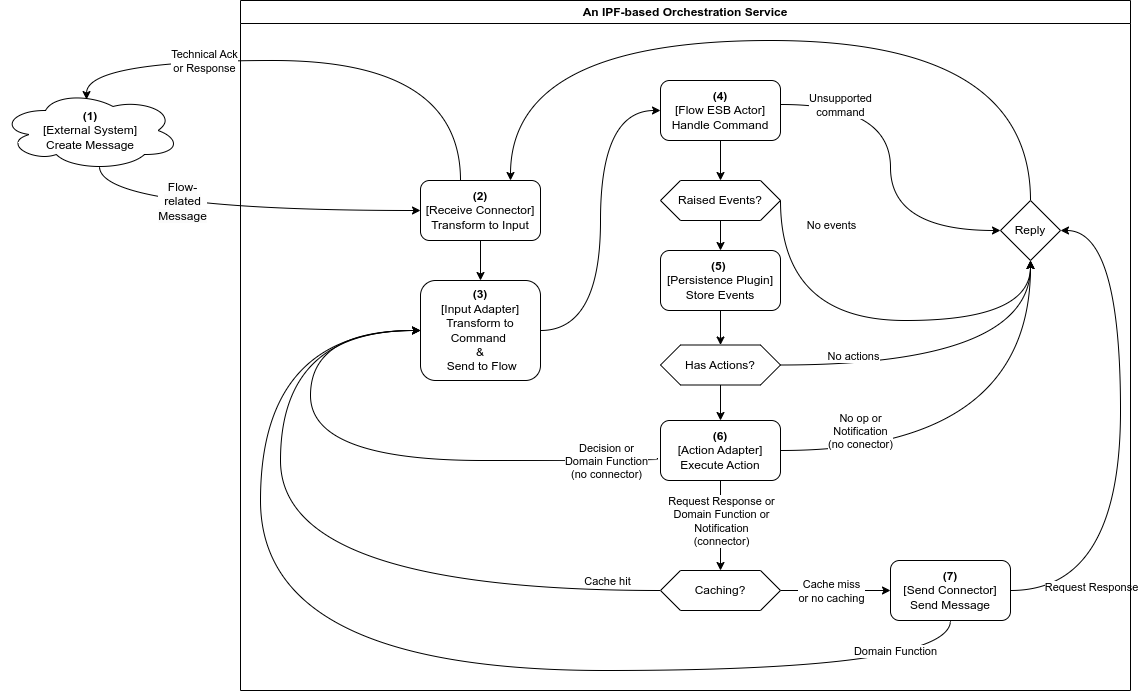
Below is a brief description of each step in the message flow. Note that, due to Akka cluster sharding, steps 1-3 and 4-7 are likely to be performed on different IPF orchestration service nodes.
-
Messages usually enter an IPF orchestration service via a
Receive Connector -
The connector transforms the received message into an appropriate
Inputand calls the relevantDomainInput Adapter -
The sole purpose of the adapter is to convert the input into a command and send it to the appropriate
Flow ESB, which may reside on a different service node -
When it receives the command, the
Flow ESBfirst checks whether the command should be applied. If the check passes, an event is persisted using the persistence plugin. If the check fails, further steps are skipped. -
(Optional)
Akka Persistence Pluginconverts the events into database write commands and communicates with the database -
(Optional) If there are configured actions (side effects) to be triggered upon event persistence, the
Flow ESBtriggers them at this point via the appropriateAction Adapter.-
If the configured action implementation models an interaction with an external system, a
Send Connectorcan be used to execute this, as shown in step 7. The choice ofSend Connectoris informed by the type of action that has been modelled:-
A Request-Response action is used — A
Send Connectoror an uncachedRequest Reply Send Connectoris used to send a message. Any potential response to that message from the external domain will be received via aReceive Connector. -
A Domain Function action is used — A potentially cached
Request Reply Send Connectoris called, meaning a configuredCache Adapteris first inquired.-
On a cache miss, the
Request Reply Send Connectorcall proceeds and the result of the operation is stored in the cache for future use. -
On a cache hit, we skip step 7.
-
-
-
If the configured action implementation represents a process that’s handled entirely within the boundaries of the domain, a
Send Connectoris not required and theAction Adapterconverts the response into an appropriateInputand calls itsInput Adapter, continuing the flow from step 3. -
If no actions are to be triggered, step 7 is also skipped.
-
-
(Optional) The connector converts the action’s data into a format that the external domain expects and sends it using the configured transport.
Backpressure
Backpressure is a means of flow-control and a way for consumers of data to notify a producer about their current availability, effectively slowing down the upstream producer to match their consumption speeds. Most reactive streams libraries offer developers several approaches (which can sometimes be combined) to use when backpressure is encountered:
-
Buffer messages
-
Slow down (throttle) the processing
-
Shed load (drop messages)
-
Take latest (head) message
Usually, backpressure applies within a single OS process (in our case, a JVM) and is most frequently mentioned in the context of reactive streams. Some messaging protocols do support backpressure as part of their specification, allowing signals to leave the confines of a single process (e.g., AMQP flow control).
Backpressure in Akka
IPF Connectors are built on top of Akka Streams, a reactive streams implementation, which comes with built-in backpressure mechanisms.
Akka actors communicate by asynchronous message passing, which by default offers no backpressure. However, backpressure can be added by applying the ask pattern, thus forcing users of any actors (which includes IPF flows) to wait for a response before proceeding further.
For flows, Akka Persistence will only allow a configurable number of flows to be initiated or rehydrated concurrently. This, in combination with the ask pattern mentioned above, acts as a protective barrier around the event store, propagating any backpressure from the database upwards.
Backpressure in DB
IPF uses the reactive streams MongoDB driver, which comes with built-in backpressure support. The MongoDB reactive client slows down on backpressure, and this backpressure is propagated to IPF Connectors and Akka Persistence.
Backpressure in Connectors
As mentioned before, IPF Connectors are built using Akka Streams, making backpressure a built-in feature.
All connector stages slow down consumption on backpressure by default, although certain stages do offer other options:
-
Source.queueis mainly used inSend Connectorsto queue up messages for sending. It buffers requests to send up to a limit, then slows down producers up to a limit. Once both limits are breached, it starts to drop messages. -
Flow.mapAsyncis used in all types of connectors to perform various potentially long-running work — mapping, logging, correlation, appending to dead letter queues, etc. It can be seen as providing a buffer of concurrently executing requests, after which it slows down the upstream.
Backpressure in IPF (All Together)
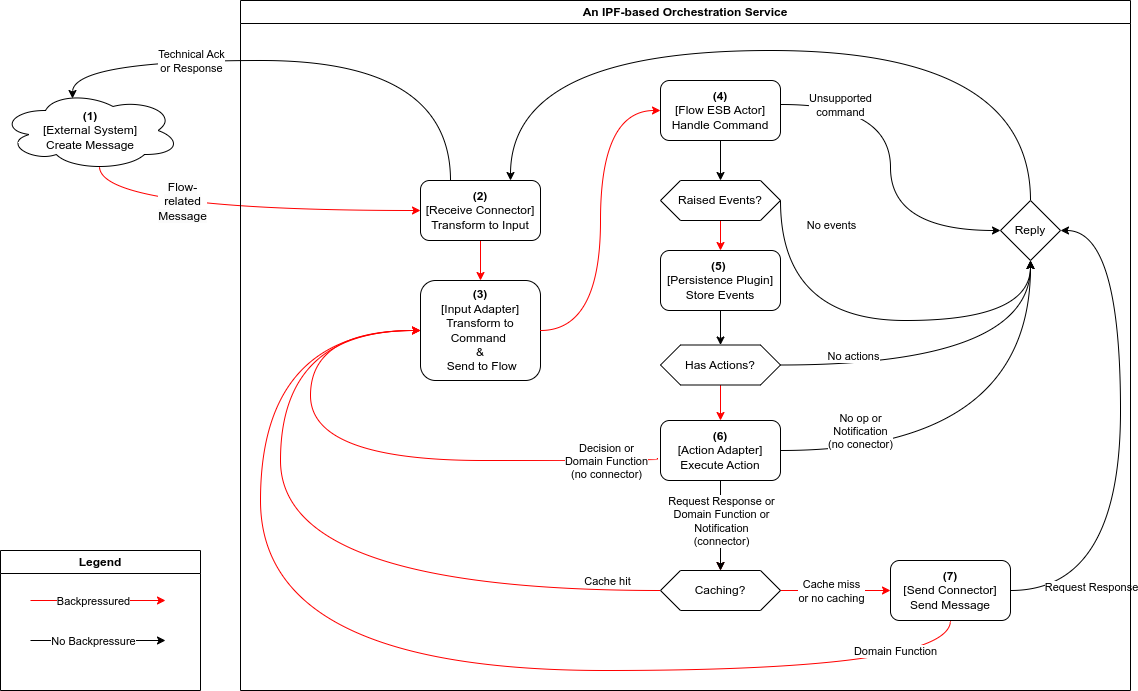
As explained in the message flow section, all IPF components are intricately linked together, causing their backpressure mechanisms to combine.
In practice, Receive Connectors serve as the main bottleneck in the IPF orchestration service, where backpressure from downstream dependencies ultimately manifests.
This means that the speed at which the Receive Connector consumes and processes work is determined by the processing speed of the entire message flow, and is no faster than its slowest step.
Backpressure flows through the service as follows:
-
An
External Systemcreates a message and has it delivered via a transport of its choice. The chosen transport influences whether backpressure signals from the orchestration service reach the external system. HTTP can shed load by returning 503 errors on backpressure, AMQP supports slowing down producers, while Kafka and JMS simply act as buffers. -
Each
Receive Connectorwill have one or more stages with a small buffer of messages that can be processed in parallel. When the buffer is full, the connector will backpressure and stop consuming new work. Messages are only removed from the buffer when their processing completes (successfully or not). Depending on the connector’s resiliency settings, processing of a failed message can be retried a configurable number of times until the max number of attempts is reached, or until the configured timeout duration elapses. -
An
Input Adapteroffers no backpressure mechanisms of its own and instead propagates downstream backpressure by awaiting confirmation — in the form of a successful processing outcome message — that steps 3-7 have completed successfully. The adapters come with their ownRetrySupport— a (retryable) failed call to theFlow ESBwill be retried a configurable number of times before the failure is propagated to the connector. -
Each call to the
Flow ESBfrom anInput Adapterwill use Akka’s support for location-transparent cluster messaging, and will wait for a configured amount of time for the processing outcome message to be received before timing out and signaling to the adapter’sRetryStrategythat the attempt has failed.Flow ESBactors process commands one by one and they buffer pending messages in their message queues. If theFlow ESBdetermines that the command should not be applied (e.g., it’s invalid for current state, a duplicate, etc.), a processing outcome is sent to theInput Adapterand further steps are skipped. -
The speed at which commands are processed directly depends on the speed at which the
Akka Persistence Plugincan persist them. Once the event is persisted, theFlow ESBis free to accept new commands. -
All configured actions that the
Flow ESBtriggers are called asynchronously and in parallel. The processing outcome is sent to theInput Adapterfrom step 2 only after all actions have been completed. -
Depending on the action type and its implementation, different backpressure rules apply:
-
Decisions do not interact with external systems, but they do result in a chained execution that effectively triggers steps 3-7 and propagates their backpressure upstream to the
Receive Connector. -
Domain Functions may require external interactions, after which a chained execution ensues, effectively triggering steps 3-7 and propagating their backpressure upstream to the
Receive Connector. -
Notifications and Request Response actions usually require external interactions, but they typically do not trigger chained execution unless they interact with a separate flow. As a result, only the backpressure from
Send Connectorswill be propagated to theReceive Connector. -
Unless they are remote or distributed in nature,
Cache Adapterstypically do not backpressure — accessing the cache is an in-memory operation. -
Both the plain
Send Connectorand theRequest Reply Send Connectorprovide a buffer for messages being sent in parallel. Once the buffer is full, it will slow down and then start dropping messages. -
Both types of
Send Connectorsupport configurable retries and timeouts, which will be included in the backpressure slowdowns.
-