DSL 1 - Introducing Icon’s DSL
Overview
You will find the following video (10 minute watch) a very helpful introduction to the basic structure of an IPF application. It also gives a high level overview of the DSL Concepts discussed in this tutorial section.
Concepts
|
This section of the tutorial introduces the concepts within Icon’s payments DSL. It is a theoretical walk through and does not require access to any IPF components. |
Business Data
We start by considering data. Data is what drives processing and decision making throughout IPF.
The first concept we consider therefore is the "Business Data Element". It has four properties:
-
A name
-
A description
-
A "data type" - the data type can be any Java type, whether it be standard classes like String, Integer etc or your own bespoke types.
-
A "data category" - an optional field, the possible values are an enumerated set that refers to the type of data that is being represented by this BusinessDataElement. This Data Category label is used by various IPF components such as IPF Data Egress and Operational Data Store, which can automatically record data captured from Process Flows automatically, depending on the Data Category. There are four core data categories:
-
MESSAGE_DATA_STRUCTURE - This is data originating from external financial messages that is often modelled as ISO20022 message components within IPF.
-
PROCESSING_DATA_STRUCTURE - This is data gathered during the processing of payments, such as meta-data and payment type information.
-
ADDITIONAL_IDENTIFIER - This applies to data elements that represent additional identifiers to be associated with the payment.
-
Any MPS project can have as many different business data elements as you need. These elements are defined within a "Business Data Library" which is simply a collection of related business data and as many different business data libraries can be defined as needed.
|
IPF provides a number of pre-configured business data libraries. By default, any process is given the "error" library which provides default elements for handling flow failures, namely:
The concepts of reason and response codes are discussed later in this document. |
Within the lifetime of a payment each business data element is unique and it can be updated as required.
Flow
The processing of a payment is performed by a "Flow". A flow represents a single business process from end to end and is designed to specify the lifetime of a single payment. A single flow might have many paths through it, each representing a different way of processing an individual payment based on the data provided for that flow. A flow contains a number of things:
-
A name
-
A description
-
A version
-
A global state set
-
A list of "States"
-
A list of "Events"
-
An "Initiation Behaviour"
-
A list of "Input Behaviours"
-
A list of "Event Behaviours"
-
A list of "Aggregate Functions"
A definition of each of these aspects are discussed in the following sections.
|
The combination of "Flow Name" and "Flow Version" uniquely identify a flow. The version is just an optional numeric identifier, so for example a flow may be called "Test" and have version 3. Then the flow can be unique identified as "TestV3". If there was no version defined it can be identified simply by the name "Test". This identifier is known as the "FlowId" |
Global States
First we consider the "Global State Set". The global state set is a set of states that represent the overall state of a payment. It is particularly used where a payment may span multiple flows (for example if the payment processing is split into "initiation" and "execution" parts) but can also apply an overall grouping type state to the individual flow parts to simplify the apparent state transitions from a payment level. Each flow level state can be mapped to a global state such that multiple flow level states can all be considered to leave the payment in the same overall global state.
|
A default global state set is provided which provides the following standard states: Pending, Accepted, Rejected, Manual Action Required and Cancelled. |
States
The next concept to consider within our flow is a "State". This is very simply a resting point on the flow that the payment can pass through in it’s journey, so for example we may have a very simple flow that goes from "State A" to "State B".
A state itself has a number of properties:
-
A name
-
A description
-
A global state
-
A terminal flag - the terminal flag is used to indicate that this ends the flow to which the state belongs.
Each flow can contain many different states.
Events
When a flow moves from one state to another, this is known as a "State Transition". Within IPF, for a state transition to occur then the system needs to receive an "Event" on the processing journey of the payment. In this case, it is actually a specific type of event known as a "Domain Event". A domain event is a persisted factual occurrence - the arrival of an event means that something explicit has occurred which may cause some form of change to the processing of our payment.
An event has a number of properties:
-
A name
-
A description
-
A list of business data elements.
When an event is formed, then the system will check it’s own behaviour to determine what actions should be performed. Whilst this behaviour is explored later in this document, it is worth noting here that there are three occasions when an event can cause a change to the processing, these are known as the "Event Criteria" conditions and are defined as:
-
On - this movement will happen upon the arrival of a single event (e.g. we may transition when receiving "Event 1")
-
On any of - this movement will happen upon the arrival of one of multiple events (e.g. we may transition when receiving either of "Event 1" or "Event 2")
-
On all of - this movement will only occur upon the arrival of multiple events (e.g. we may transition only after receiving both "Event 1" and "Event 2")
|
Here we have described the "Domain Event" which is the type of event that is explicitly declared within any MPS solution. However, IPF as a whole uses a number of different types of event:
All these event types are discussed later in this document. |
External Domains
After an event is processed, the application can then perform one or more activities to determine what happens next on a payment. So for example on receipt of "Event A" we may wish to do some validation and call some other application to ask it to validate our data.
To support this post-event processing, the most important concept is the "External Domain". This represents some business domain - not our current flow’s - that we need to interact with.
For example, let’s assume that we need to talk to a sanctions system during part of the flow. To support this, we would model that sanctions system as an external domain.
Each external domain consists of the three types of interaction we can make with it:
-
"Instructions" - instructions are the simplest thing we receive from an external domain. It can be triggered by the external domain at any time and we will start processing. This can be thought of as the external domain pushing information to us.
-
"Notifications" - notification are the opposite of instructions. These are used when we want to push our data out to an external domain.
-
"Requests" - a request is used when we need a "response" back from the external domain in reply.
Instructions
Firstly let’s consider the instruction. These can be initiated by an external system and contain the following properties:
-
A name
-
A description
-
A list of "Business Data Elements"
When the IPF application receives an instruction it will raise a corresponding event (the decision of which event to raise is described later). The event’s business data is then populated with all the matching business data elements.
Notifications
Next up is the notification, like an instruction it has the following properties:
-
A name
-
A description
-
A list of "Business Data Elements"
When the IPF application sends out a notification it will populate on it all the business data elements it has a matching record for.
Requests
Finally, we consider the requests. The request can be thought of to have to parts, the request itself and the corresponding response.
The request part contains:
-
A name
-
A description
-
A list of business data
-
A list of responses
The response part is slightly different and has some new features to consider:
-
A name
-
A description
-
A list of business data
-
A "response code set" - this is a group of response codes. A "Response Code" is an expected outcome code for a response that could be used for onward processing. In ISO terms this is analogous with a Status.
-
A "reason code set" - this is a group of reason codes. A "Reason Code" is a reason why the response is set the way it. So for example your response code could be "Rejected" with a reason "Incorrect Currency". In ISO terms a reason code with a Status Reason.
-
A completing flag - this defines whether the calling request should be considered completed when this response arrives. So for example consider a request where the external system sends a technical acknowledgement following by a final business response. In this case we would define two responses - one to represent the technical ack (non completing) and one the business response (completing).
|
In ISO terms, a response code is analogous with a "Status", whilst a reason code is analogous with a "Status Reason" |
|
The system provides a default "AcceptOrReject" response code set which is used for standard pass / fail type responses. It also provides a set of all the ISO reason codes. |
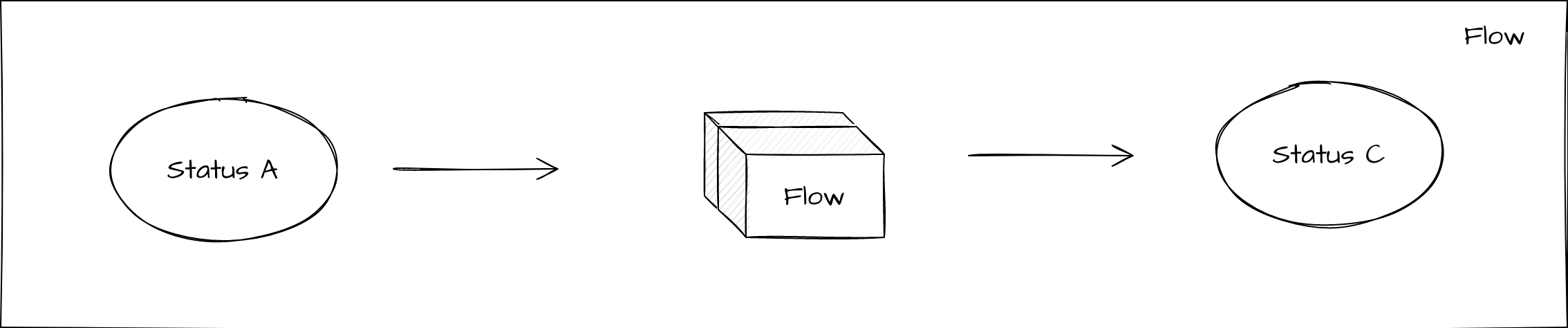
Now let’s put these elements together and form the basis of any flow:
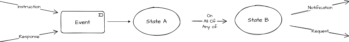
So here we can see that when IPF receives something from an external domain (either an instruction or a response), it leads to an event being raised which may cause a state transition followed by the invocation of a notification or request to an external domain.
Domain Functions
It’s possible that we don’t want to have to call an external domain in order to continue processing our flow. This might happen because either we know what to do next or we can calculate what to do next. For this there are two other concepts that we need to consider:
In this case, one option is to use the "Domain Function" capability that the flow itself offers. It works in a very similar way to a request / response pair in an external domain call except that in the case of a domain function the IPF application itself is a domain so the actual call stays internal (consider for example creating an external domain that represents our current flow - this would work the same way as a domain function but would be a mis-representation of the actual control logic). So when we call a domain function, we will expect to get a response and then that response will be transformed into an event which can then cause onward processing.
Like a request, the domain function has a number of properties:
-
A name
-
A description
-
A list of business data
-
A list of responses
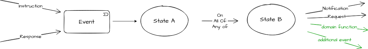
Additional Events
The second option is an "Additional Event"- these can also be used to move the flow on.
When an additional event is raised, the system will process it as though it has been received into the application via an instruction or response.
Let’s add these to our diagram:
Decisions
What however if we want to perform some logic conditionally. So for example, we may only want to run a fraud check if the value of the payment is over £50. In this case we can use a "Decision".
A decision allows us to perform some logic and then take different processing routes subsequently based on the outcome of that decision. A decision has a number of properties:
-
A name
-
A description
-
A list of business data - this is the data that is sent when calling the decision so that it can process based upon it.
-
A list of "Decision Outcomes" - these are the possible results of running the decision, each decision can have as many different outcomes as needed and these outcomes are unique to the decision. They are defined simply by providing a name.
The decisions themselves are stored within a "Decision Library". The libraries are flow-independent and as such the same decision can be used in multiple flows.
We can use a decision in two places:
-
To determine which event needs to be raised in response to an input (response or instruction)
-
To determine which actions need to be performed after a state transition.
Lets add these to our diagram:

| A special type of event "A Decision Outcome Event" will also be raised so that the fact the decision has been invoked and a result returned will be audited and can be used on onward processing. |
Aggregate Functions
Another useful utility to consider is the "Aggregate Function". An aggregate function is a piece of logic that can be executed upon receipt of an event to perform some kind of logic upon the data received. This data is considered "in flight" and thus is not persisted by the application.
So a good example of this is say a counter that tracks the number of times something has occurred during a flow - each time the function is called we may update that counter. The outcome of the aggregate function then becomes available down the flow.
Another good use case may to perform a data mapping exercise to transform the data into something that can be used downstream.
Let’s add the aggregate function to our diagram:

Behaviours
The next concepts to consider are both types of grouping. In order to separate the logic we need to define when processing an input to the system (from a response or instruction) and generating the event to the logic required when processing the actual behaviour of the system based off that event we have two grouping concepts:
-
"Input Behaviour" - this is a the behaviour that specifies for each input what event will be generated.
-
"Event Behaviour" - this is the behaviour that specifies what actions should be taken on receipt of an event.
Input Behaviour
An input behaviour has a number of properties:
-
An input - this is the input (instruction or response) upon which the behaviour is triggered.
-
A response code - this is the response code (linked to the response if the response is an input, otherwise this field is not applicable) for which the behaviour applies
-
An event - this can be either an event directly or via the execution and resulting outcome of a decision.
| Note that when using response codes, if one is not defined on an input behaviour this will be considered the "default" behaviour for all response codes. |
Event Behaviour
The event behaviour is a little more complicated. It has a number of properties:
-
A "Current State" - this is the state upon which the flow must be in for the behaviour to apply.
-
A "Criteria" - this is when the behaviour applies ( on / on all of / on any of)
-
A list of events - one or more events, these can be any type of event (e.g. domain, timeout etc)
-
A "Move to State" - the destination state of the behaviour
-
A list of actions - these are the actions that should be performed after the state transition, i.e. requests, notifications etc.
Lets update our diagram to show these:
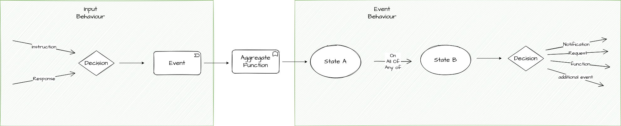
| Note that the aggregate function, as a self contained unit of calculation is not considered as either the event or input behaviour but as a functional capability of it’s own |
Initiation Behaviour
There is one more key type of behaviour to consider, that is the "Initiation Behaviour". The initiation behaviour is a specialised version the previously defined input behaviour but is only used to start a flow. It is not linked to an external domain so that we can initiate the flow potentially from many different sources.
An initiation behaviour has a number of properties:
-
A list of business data
-
An initial state to move to
-
A list of actions to perform
|
Note that when the initiation behaviour is invoked, a flow will start and the "FlowInitiated" event will be raised. |
We have now reviewed all the components that make up a single flow.
Subflows
The next thing to consider is reusable segments of flow.
For example, consider a sanctions check that may be required to be called from various different places within the flow. We could specify each section of the flow separately and write out the logic each time but ideally we would like to be able to simply reuse common logic each time. This is where the "Subflow" concept is introduced.
A subflow is a reusable flow component. It is essentially the same as a flow in that it has states, input behaviours and event behaviours. However, a subflow has no life of it’s own and is only used as a mechanism of reuse and therefore MUST be contained within an outer flow. When calling a subflow it is very similar in behaviour to receiving an event:
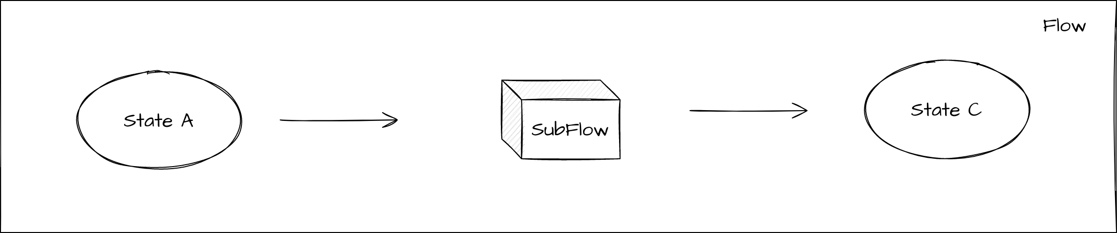
The key thing to understand here that is instead of moving to a state and then calling an action like the normal processing above, here we move to a pseudo-state that acts as an entry point into the subflow. "Control" of the flow is then handed over into the subflow, at this point it will process through the input and event behaviours until it reaches a terminal state in the subflow. When it reaches a terminal state, control will be passed back to the calling flow with a result of the name of the terminal state. This can then be used for onward processing.
Note that in order to achieve reuse of the subflow in multiple places, then when a subflow is placed within a main flow it’s state’s will be displayed as "<subflowid> <subflow state name>" where <subflowid> is the psuedo-state name of the calling flow and <subflow state name> is the name of the state within the subflow.
Flow Calls
Finally, it’s also possible to directly call one flow from another. In this case control is handed over to the secondary flow and we wait for a result execution back. The child flow can report that it has reached any state back to the parent flow. Most commonly, this will be when a terminal state is reached and the child flow has finished processing, but it also allows for feedback from the child flow for intermediary states before it finishes. This provides an opportunity to pass control back and forth between the child and parent as required.
Conclusions
In this section, we have discussed the core concepts that make up the Icon payments DSL and how they fit together. These concepts will be key going forward and the next sections of this tutorial series starts to take us through how to use different ones of these to create our payments application!