Introduction to State Machines in IPF
The payments DSL allows clients to define flows using state machines. For people who are familiar with the UML V2 concept of state machines, IPF supports a subset of UML: for example, only "on transition" actions are supported and while IPF doesn’t support parallel substates (or substates at all) it does allow multiple transition actions to be triggered in parallel. This page is intended for people who will be working with IPF who did not understand the previous sentence, because they are not familiar with the concept of state machines.
A finite-state machine (FSM) or finite-state automaton (FSA, plural: automata), finite automaton, or simply a state machine, is a mathematical model of computation. It is an abstract machine that can be in exactly one of a finite number of states at any given time. The FSM can change from one state to another in response to some inputs; the change from one state to another is called a transition.
An FSM is defined by a list of its states, its initial state, and the inputs that trigger each transition. Finite-state machines are of two types — deterministic finite-state machines and non-deterministic finite-state machines, IPF only supports deterministic finite-state machines.
The behaviour of state machines can be observed in many devices in modern society that perform a predetermined sequence of actions depending on a sequence of events with which they are presented. Simple examples are: vending machines, which dispense products when the proper combination of coins is deposited; elevators, whose sequence of stops is determined by the floors requested by riders; traffic lights, which change sequence when cars are waiting; combination locks, which require the input of a sequence of numbers in the proper order.
Example: Coin-operated Turnstile
An example of a simple mechanism that can be modelled by a state machine is a turnstile. A turnstile, used to control access to subways and amusement park rides, is a gate with three rotating arms at waist height, one across the entryway. Initially the arms are locked, blocking the entry, preventing patrons from passing through. Depositing a coin or token in a slot on the turnstile unlocks the arms, allowing a single customer to push through. After the customer passes through, the arms are locked again until another coin is inserted.
Considered as a state machine, the turnstile has two possible states: Locked and Unlocked. There are two possible inputs that affect its state: putting a coin in the slot (coin) and pushing the arm (push). In the locked state, pushing on the arm has no effect; no matter how many times the input push is given, it stays in the locked state. Putting a coin in – that is, giving the machine a coin input – shifts the state from Locked to Unlocked. In the unlocked state, putting additional coins in has no effect; that is, giving additional coin inputs does not change the state. However, a customer pushing through the arms, giving a push input, shifts the state back to Locked.
The turnstile state machine can be represented by a state-transition table, showing for each possible state, the transitions between them (based upon the inputs given to the machine) and the outputs resulting from each input. In IPF Inputs are Domain Events and Outputs are Actions.
| Current State | Input | Domain Event | Next State | Output | Action |
|---|---|---|---|---|---|
Locked |
coin |
Valid Coin Inserted |
Unlocked |
Unlocks the turnstile so that the customer can push through. |
Unlock |
push |
Turnstile Rotated |
Locked |
None |
||
Unlocked |
coin |
Valid Coin Inserted |
Unlocked |
None |
|
push |
Turnstile Rotated |
Locked |
When the customer has pushed through, locks the turnstile. |
Lock |
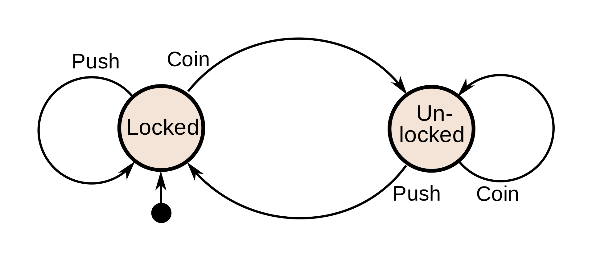
The turnstile state machine can also be represented by a directed graph called a state diagram (below). Each state is represented by a node (circle). Edges (arrows) show the transitions from one state to another. Each arrow is labelled with the input that triggers that transition. An input that doesn’t cause a change of state (such as a coin input in the Unlocked state) is represented by a circular arrow returning to the original state. The arrow into the Locked node from the black dot indicates it is the initial state.
Concepts and Terminology
A state is a description of the status of a system that is waiting to execute a transition. A transition is a set of actions to be executed when a condition is fulfilled or when an event is received. For example, when using an audio system to listen to the radio (the system is in the "radio" state), receiving a "next" stimulus results in moving to the next station. When the system is in the "CD" state, the "next" stimulus results in moving to the next track. Identical stimuli trigger different actions depending on the current state.
In some finite-state machine representations, it is also possible to associate actions with a state:
-
an entry action: performed when entering the state,
-
an exit action: performed when exiting the state,
-
a during action: performed whilst in the state,
-
a transition action: performed when entering the state by a particular transition
IPF only supports transition actions and so it’s actually the combination of previous state, new state and event that determines what the action is that is carried out on entry, it is not defined as part of the state. To enable parallel processing, multiple actions can be triggered by a domain event. For example, in the table above the first row could as well as having the action "unlock" have a second action "play welcome sound" to be carried out in parallel with unlock.