Flo-Lang Generation
Generation Basics
Let’s now consider the what happens after we have modelled our process and how we can use this to generate applications.
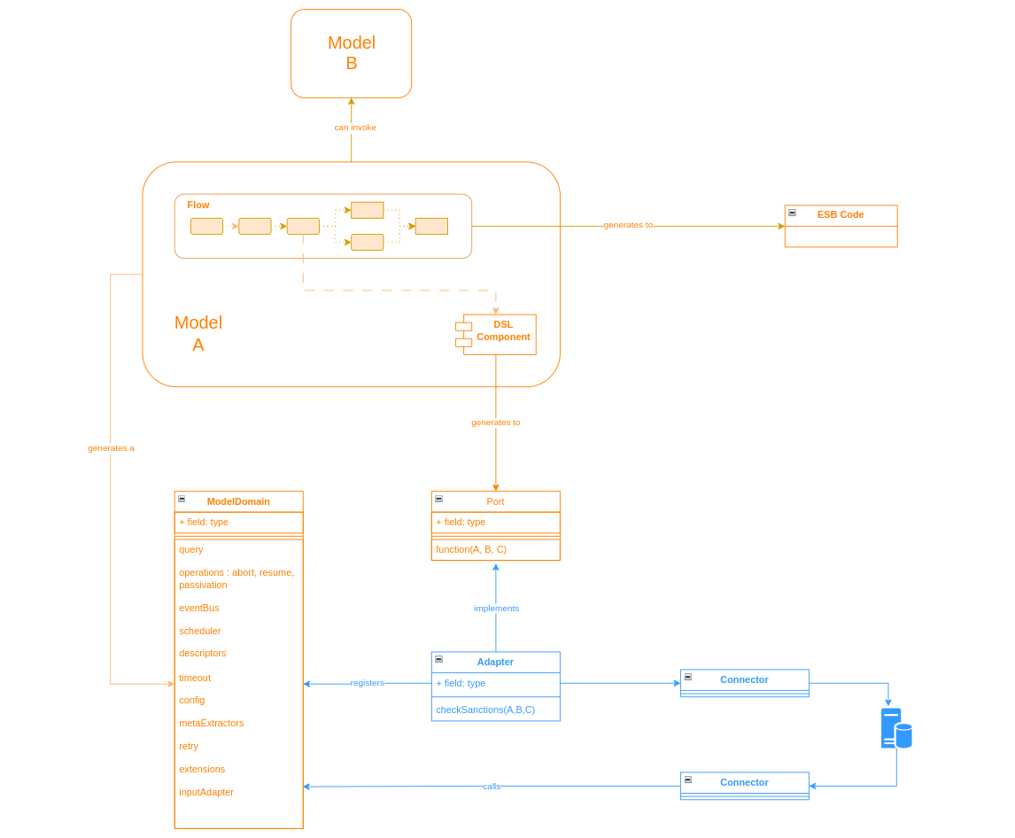
So suppose, we have built a simple model such as:
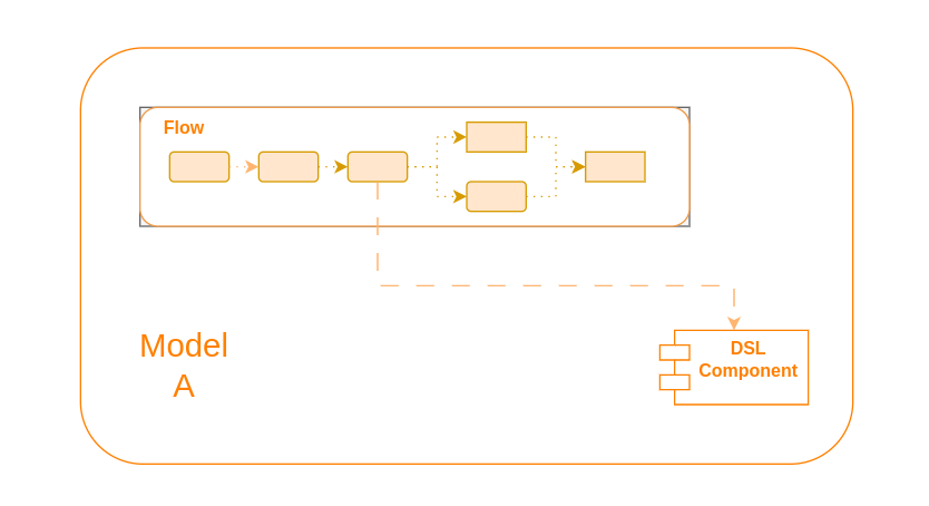
Here we have a single model containing our flow which at some point calls a DSL component. This could be any of the components discussed in the concepts section, for example an external domain call.
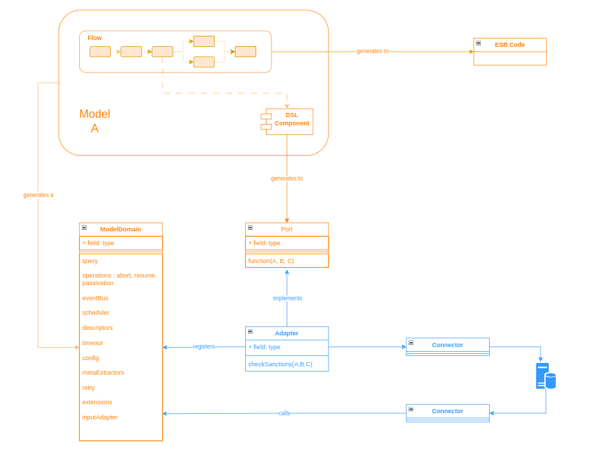
When generation is invoked on this model we will see a number of key artifacts created.
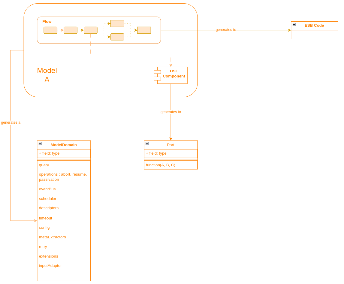
Here we can see that there are three key things to be aware of during the generation process:
-
The ESB Code - this is the Akka Event Sourced Behaviour. It’s the engine that really drives the underneath processing of a flow as it receives the various inputs throughout the lifecycle.
-
The ModelDomain class - this is the central point used to interact with the IPF modelled domain. It has key operations that provide all the support needed to work with the generated flow.
-
The Port classes - each DSL component that is used will generate it’s own port (interface). This is what the ESB Code will invoke at the relevant times during flow processing and allows for the provision of the business logic required for that call.
|
Note that in the above for brevity not all generated artifacts are listed. There are many others, such as the test stories and asciidoc files. |
Working with the Generated Code
From a client perspective there are three main things that need to be done to use the generated code:
Providing the Adapters
Firstly, for each generated port we need to create an adapter. The adapter is the implementation of that port definition.
Adapters can create as much or as little code as you wish. A typical use case for an adapter might be to take the information provided and send it on to a downstream system. If you’re using the connector framework for this, that could be as little as a single line of code!
|
One of the generated artifacts is the 'sampleapp'. This contains dummy implementations of all the ports produced. So it’s not necessary to build them all at once, you can just create any you need now and use the sample ones for everything else! |
Building the Domain
Having built our adapters, we need to now build our domain. To do that we simply need to call the builder for it. If you used the archetype to construct your project this is already done for you. But if not, we simply do something like:
@Bean
public ExampleDomain exampleDomain(ActorSystem actorSystem) {
    return new ExampleDomain.Builder(actorSystem).build();
}|
Here we’ve done this as a spring bean, but that is not required and is mainly for consistency with other techniques generally used throughout IPF applications. |
Registering the Adapters
Finally, we also need to register the adapters with the domain. For this, the domain class has a simple withXXX method for each adapter it’s expecting. So we simply extend our domain definition and register our adapters like:
@Bean
public ExampleDomain exampleDomain(ActorSystem actorSystem, ExternalDomainPort externalDomainAdapter) {
    return new ExampleDomain.Builder(actorSystem)
    .withExampleExternalDomainPort(externalDomainAdapter)
    .build();
}
Let’s complete our diagram with the new parts, noting the sections in blue are what we are expecting to be client code:
Working with the Domain
Now we’re all set to go and we can start using our model domain class to interact with the flo. For example, we have the 'initiation' utilities to allow us to start a flow, so we might do this by using:
ExampleDomain.initation().handle(someInitiationInput);|
In order for the domain to work, it is necessary to provide all the adapters to the flow at startup. For this reason, IPF performs a validation check and will now start up if adapters are missing. |
Working with Other Models
It’s also possible to have a component from one model call a component from a different model.
For example, an external domain could be packaged into a common reusable model and then be called across many different implementating flows.
In this situation, all that needs to be done is that each model is seperately created and defined just as described above. That’s it! All the logic around interactions between the two are taken care of by the framework.
So to finish up lets add our remote model into the diagram: